Categories
3d printing CAD - Design Project

Bobble Heads

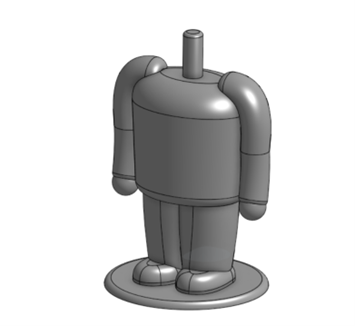
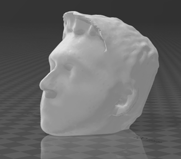
For one of the IDEA Lab events, I decided to make bobble heads of your head for my workshop. I first designed the bobble body using OnShape. This was the body that all attendees were given. To create the head, I first used the Structure Sensor Pro to scan the attendee’s head using the Structure Scanner app on an iPad to create an STL model. I sent the model to my computer and opened the STL file in Microsoft 3D Builder. I edited the model to fit the springs and connect to the body. I used the Prusa MK3S print farm to print the bodies and heads.

Equipment/Software:

  • OnShape
  • Prusa MK3S
  • Microsoft 3D Builder
  • Structure Sensor Pro
  • Structure Scanner App
  • iPad Pro 10th Generation
  • Springs

Step by Step:

  • Designed the body in OnShape
  • Create a scanned head using the iPad scanner, and sent to 3D Builder
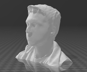
  • Trim the head
  • Import the bobble spring attachment, which is the negative that will be subtracted from the inside of the head
  • Export the model and import the body and head into PrusaSlicer
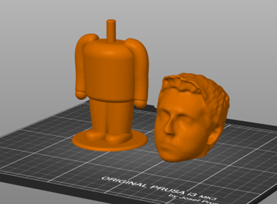
  • Assemble the design, cut spring in half and hot glue the head to the spring, and the body to the spring
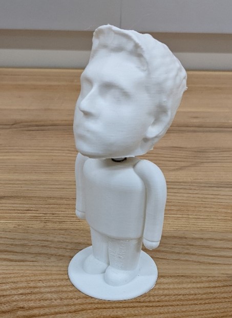
The challenging part with this project was to find a simple way to add the spoke for the spring to attach to within the head. At first, I tried to subtract a cylinder hole from the head, then add another cylinder for the spring to attach to. The issue with this was that it was difficult to get the spoke and hole to get the correct dimensions each time. I then came up with a solution by creating the negative space of the hole and spoke in CAD, and then subtract the negative from the head. This left the spoke and hole the same for each head.

Through the development of this workshop, I learned a more in-depth usage of CAD programs; problem the creation of more organic models (arms in the body). I also learned more techniques in creating 3D scans of people’s heads and further modifying them to fit our needs.

Categories
3d printing CAD - Design machine shop Programming Project

Prusa Print Farm

by Trevor Neal and Bryan Bushey

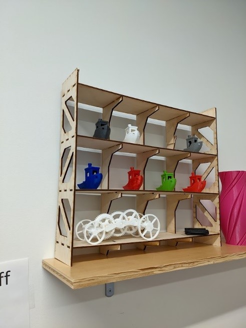
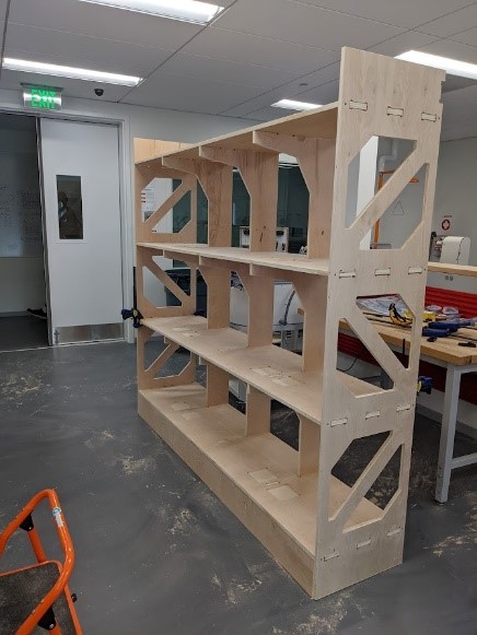
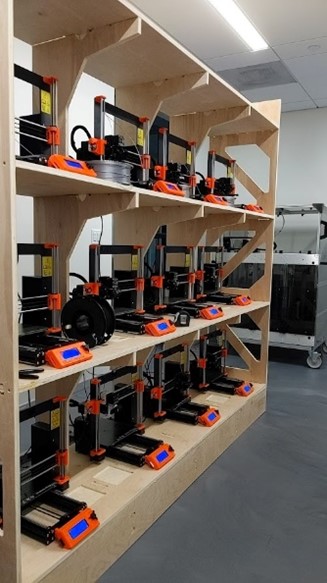
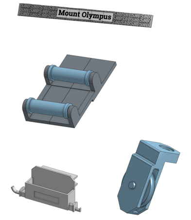
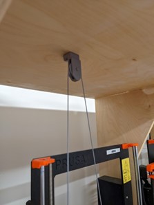
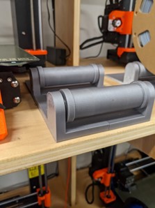
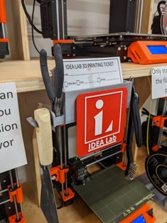
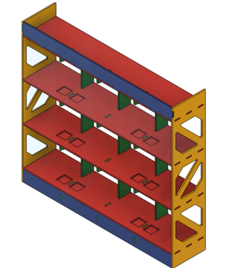
For the arrival of 12 new Prusa MK3S+ 3D printers, we needed to design a system to streamline the 3D printing process for new and returning users. We created a large shelf to store the printers by first using Fusion 360 to implement the design. We then created a scale model to accurately determine measurements. Next, we cut on the lab’s ShopBot CNC machine. Once all the pieces were cut, we assembled the shelf and sanded at 220 grits. Applying a polyurethane finishing after. When the wall was complete, we designed 3D printed filament spool rollers and pulleys to allow easy access for changing the printer’s filament. After, we designed a 3D printed sign to label our print farm, “Mount Olympus”, since we named all 12 of our printers after the 12 Greek Gods.
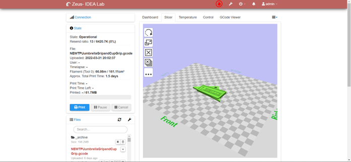
            Our goal with the usability of the print farm was to create an online website that allows users to select one of the lab’s Prusa 3D printers, upload their model, have it sliced using our custom profile, and automatically start the sliced print. We decided to use OctoPrint. OctoPrint is a fully open-source web server/interface to directly connect to a 3D printer. Originally, OctoPrint was designed to be installed on Raspberry Pi computers, since we had 12 printers, we wanted one system to do everything.

Equipment/Software:

  • Fusion 360
  • OnShape
  • ShopBot
  • Epilog Fusion Pro 48 Inch
  • 3mm Plywood
  • ¾ inch Plywood
  • Linux Docker
  • OctoPrint
  • Overture PLA
  • 22mm Ball Bearings

Step by Step:

  • Designed the shelf in Fusion 360 and exported the file as a DXF
  • Laser cut out a scale model on the Epilog Fusion Pro in wood, using 3mm plywood
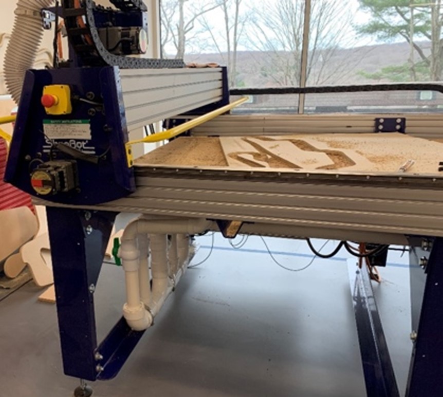
  • Cut out the finished design on the ShopBot using ¾ inch plywood
  • Assemble the cut design (nail gun/wood glue/sanding 220 grit)
  • Finished wood with polyurethane
  • Designed spool rollers, pulleys, and wall-sign in CAD
  • 3D printed designs and installed on the shelf
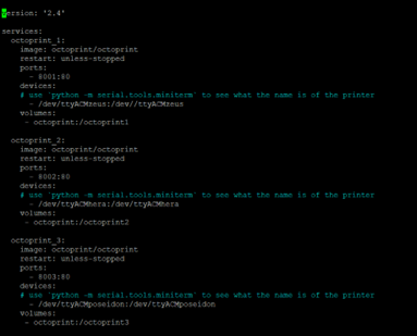
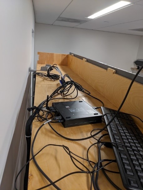
  • Computer formatted to run Linux, with Docker instances installed

Using a standard desktop computer, we downloaded and installed Debian Linux to run 12 different docker instances of OctoPrint designed specifically to work for docker.

  • Create profiles for OctoPrint on each instance and install the web slicer
  • Connect printers to their respective instance
  • Create website using HTML, CSS, JavaScript

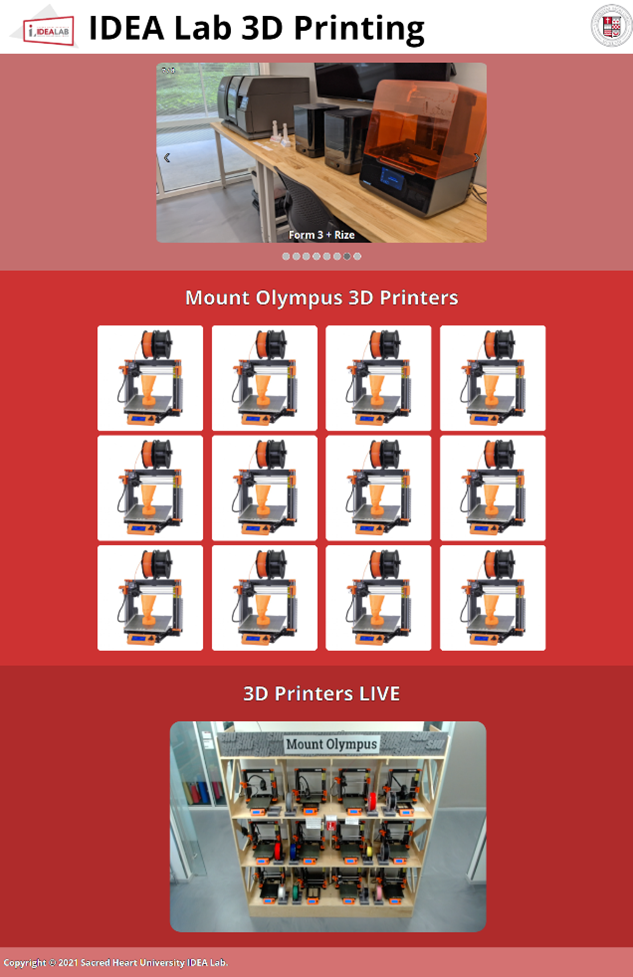
To make using the print farm easier to the end user, we created an HTML page that displayed links to each of the instances as well as a live webcam feed to visually monitor the printers.

  • Webcam installation

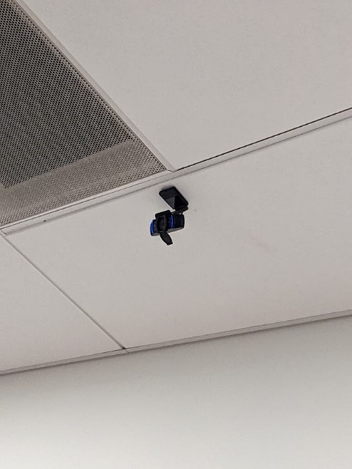
We wanted to also create a live webcam feed to accurately monitor on-going prints. To do so, we connected a webcam to the Linux computer and created a new docker instance for the webcam.

  • Finished

One of the main challenges with this project was to get the computer functional with 12 instances of OctoPrint using Docker. We continued to run into problems on getting the OctoPrint slicer plugin to be functional. We overcame this by researching documentation on the slicer plugin and found the correct install information for Linux. Setting up the webcam had its own issues. When creating the webcam Docker instance, the recommended image file we decided to use did not function correctly, so after trying newer images, one finally produced the results we were looking for.

During this project we learned many new and innovative ways to create a 3D printing farm. For us, we learned a lot about how docker, and its instances work on Linux systems. Creating the website allowed us to learn HTML, CSS, and JavaScript together.

Categories
3d printing CAD - Design machine shop Project

Front Desk at the Makerspace

by Bryan Bushey and Trevor Neal

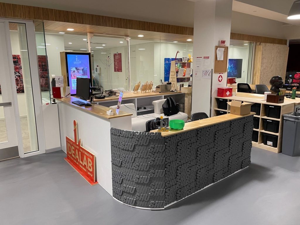
We designed the front desk of the makerspace at Sacred Heart University by using the Fusion 360 CAD software and the CNC Router known as the ShopBot. This wooden desk is used each day by staff as a receptionist desk. The second part of the desk is used for staff storage, and it holds a welcoming monitor for visitors.

Equipment/Software:

  • Autodesk Fusion 360
  • ShopBot
  • Epilog Fusion Pro 48 Inch
  • ¾ inch 4ft x 8ft Plywood
  • 3mm 12in x 24in Plywood

We designed the front desk using Fusion 360 keeping the thickness of the stock and multiple other measurements as ‘parameters,’ allowing us to alter the measurements seamlessly depending on future need-based changes. Some difficulties were that the wood sourcing in the design phase vs the final product. When we initially designed the desk there was supposed to be a sheet of butcher block. After some logistical challenges, we ended up deciding on a single ¾ inch sheet with stain to give it a polished look. The sides were painted white to match the surrounding room.

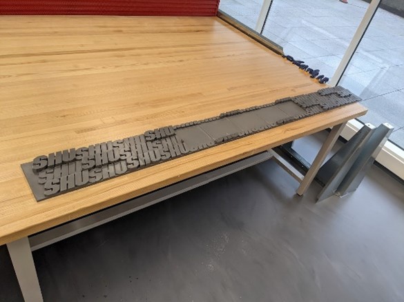
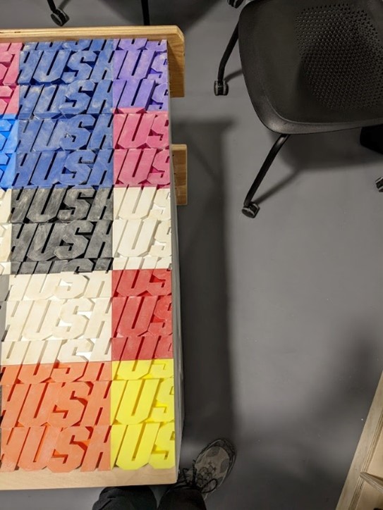
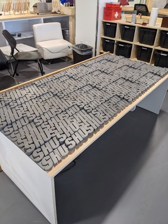
We worked on the 3D printed SHU wall that wraps around the model. To get the ‘SHU’ wall to look flush, we had to sand the entire face and apply multiple coats to get a smooth even finish. We only had a 3D printer bed size of no more than 12 x 12 inches, we had to slice the wall into 50 separate pieces for the flat section alone, and 24 pieces for the curved section.

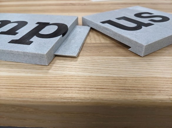
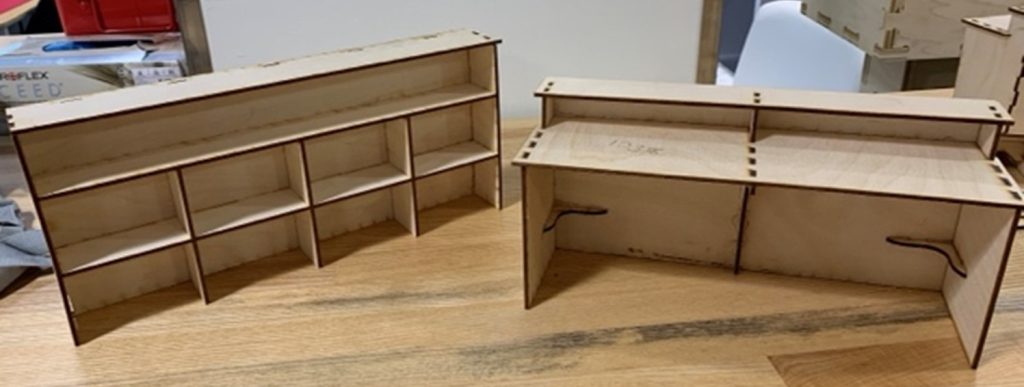
To ensure the finger joints were appropriately placed, we cut out scale models. By scaling the 3/4in plywood to the 3mm plywood, the models were the exact proportions that the final product would be.

The main challenge was keeping in mind all the add-ons like the monitor and outlets. When designing it is easy to forget about the real-world parts that play into the design after it is built. Also being one of my first major CNC projects with the ShopBot, we did not have much experience with tolerances. By designing the CAD model with an exact thickness of 3/4 of an inch, it was harder to fit the finger joints together as there was zero give between parts. For this project on we used 18mm as the thickness because it allowed for a more forgivable distance that was more realistic.

Categories
3d printing Project

Words Matter Art Pieces

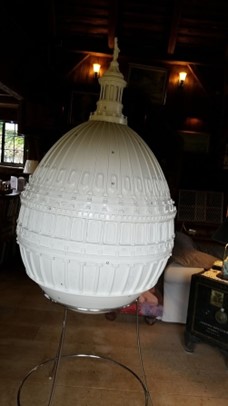
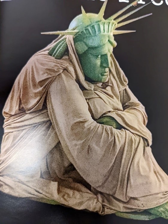
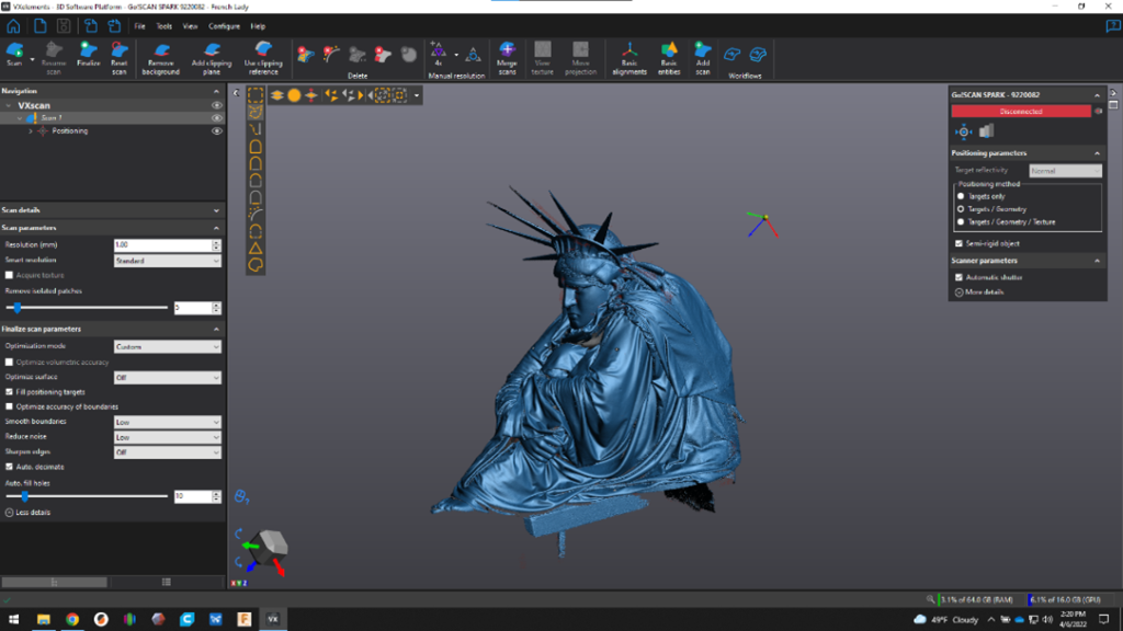
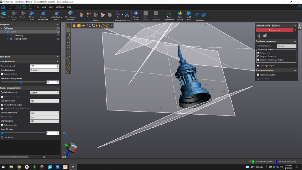
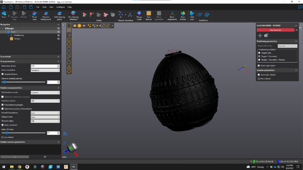
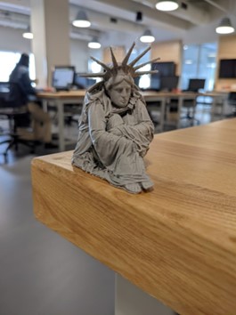
I was tasked with assisting Artist Mark Yurkiw in creating 3D scans of two of his art pieces, Yearning to Breathe Free, and Re-Birth of a Nation. The scans were modified to create miniatures of the art pieces to raise funding for the @#1 Main St. Galley Inc. a 501c3 non-profit raising awareness for local artist to local people. Yearning to Breathe Free will be sold at fundraisers and venues for the homeless as thank you gifts at certain donor amounts. Re-Birth of a Nation will be sold for fund raising events for children’s cancer research. I took the high-resolution scans using the Creaform Go!SCAN Spark 3D Scanner and modified the raw scans in Creaform’s VXelements program. For other modifications, I used Microsoft 3D builder, for example, the spokes on the Statue were too thin, so I used 3D builder to extrude the spokes. Originally, I 3D printed the prototype models on our Prusa MK3S and Ultimaker S5 printers, once I saw the quality of the prints, I determined that we should use SLA printing for a higher, more detailed resolution. We used the Formlabs 3+ and the Elegoo Mars 2 Pro for these demo prints.

Equipment/Software:

  • Creaform Go!SCAN Spark 3D Scanner
  • Creaform VXelements
  • Microsoft 3D Builder
  • Prusa MK3S
  • Ultimaker S5
  • PLA
  • Elegoo Mars 2 Pro
  • ABS Mint Resin
  • Formlabs 3+
  • White Resin

Step by Step:

  • The original art pieces to be scanned
Re-Birth of a Nation
Yearning to Breathe Free
  • 3D Scanned the two art pieces with the Creaform Go!SCAN and edited the models in VXelements
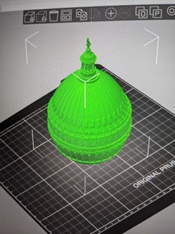
  • Re-Birth of a Nation in Prusa Slicer
  • 3D printed using FDM technology, lower detail
  • 3D Printed using SLA technology on Elegoo Mars 2 Pro, higher detail

During this project, the most challenging aspects were learning how to use SLA 3D Printing technology and learning to use the VXelements program to successfully scan objects in 3D.

Through the months working on this project, I learned the process of creating resin printing and understood what goes into creating a successful 3D scan, fully ready to be 3D printable.