This training will teach the user how to use the Carvey CNC Router specifically for the purpose of creating custom one-sided PCB boards. After this training, the user should feel confident in uploading PCB designs, switching the drill bits, and working the Carvey.
This training includes:
-How to use FlatCAM to prepare your Gerber, Excelleon, or G-code file for use with the Carvey
-How to use CorelDRAW to prepare your SVG file for use with the Carvey
-Where to find PCB supplies and which tools are needed
In order to take this training, one must complete the general Carvey Training first and taking either the Fritzing PCB Training or Fusion 360 PCB Training is also recommended.
Using the Carvey for PCB
When using the Carvey to make a PCB board, you will need to use software such as Fritzing or Fusion 360, to make the design, and then you must import it into Easel. This will either be in the form of an SVG file or g-code, in this case, g-code is preferable.
FlatCAM
FlatCAM is a software that allows users to take their designs and prepare them for use with a CNC router. This training on FlatCAM will allow users to take their PCB design files that are Gerber, Excellon, or G-code and prepare them for use with the Carvey CNC Router. (For important things to keep in mind look at the Cheat Sheet)
Preparing a One-Sided PCB:
-Importing file for isolation routing
-Importing excellon file for drilling
-Importing contour to cut out
-Importing g-code files to Easel
CorelDRAW
CorelDRAW is a vector graphics editor. If you can export your PCB design to an SVG then you will need to edit and prepare those SVG files for the Carvey so that your PCB prints correctly. The following video shows how to do this starting with a Fritzing project, but this step can be skipped if the SVG files are already available. (For important things to keep in mind look at the Cheat Sheet)
Preparing SVG File for Carvey:
-Exporting Fritzing to SVG
-Different Export Files
-Editing the copper bottom mirror SVG
-Editing the copper top mirror SVG
-Importing SVG files into Easel
-Preparing Easel for cutting
Important Notes:
- To make a PCB we use copper because it is highly conductive.
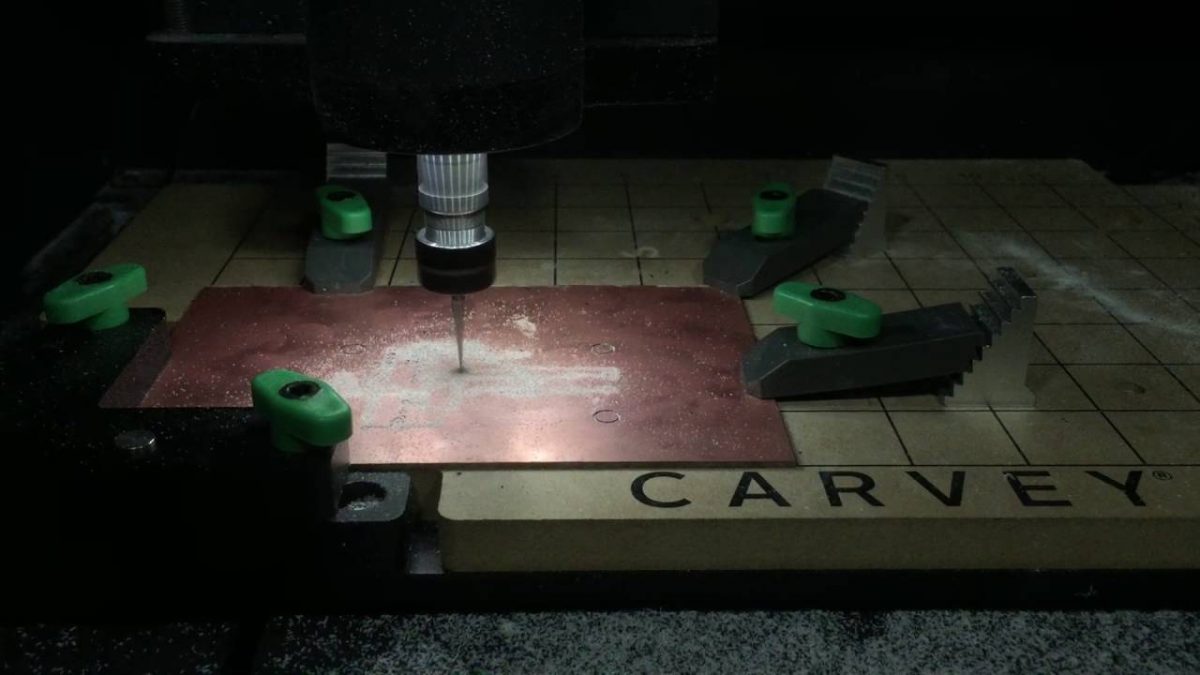
- Because we use copper, we must make sure that the Carvey is engraving the outlines of the wires, not the wires themselves. In order to create a connection, the wire must be intact between the parts being connected.
Example: Notice how the cuts are around the “wires”

- Make sure the bit size is correct and small enough (.2 mm works best for cutting out PCB and .1 mm works best for engraving the wire marks)
- Make sure when changing the bit to drill the through-holes that you are using a drill bit and not a carving bit (drill bits have a colored collar around them)
- Check the size and thickness of the material (most PCBs are 1.4 mm to 2 mm thick – use the caliper)
- When uploading g-code all material and bit sizes must be specified in the g-code, it CANNOT be edited in Easel once the g-code is uploaded.
- Because the PCB board is so thin, use the green clamps to secure the board
- Check the depth of cut when engraving the wires (only need to take off the copper, don’t want to go all the way through).
- Make sure that when drilling the pinout holes you set the thickness of the material to be a little thicker to ensure the holes are big enough on both sides of the PCB
Videos of Carvey in Action
Carvey Engraving PCB:
-Shows the Carvey breaking the copper in order to create the connections needed
Carvey Cutting Pinout Holes:
-Shows the Carvey creating the pinout holes by using a small (.2 mm) bit to create the holes
Carvey Cutting Out PCB:
-Shows the Carvey cutting out the fully engraved PCB with pinout holes
Take the Quiz!
Cheat Sheet
General Notes
- Measure material size and thickness
- Check the cut path if applicable
- Make sure that everything is inputted right into the software (Easel , Fusion 360, etc.)
- Keep in mind the file type being used (i.e. Gcode (can’t be edited once in Eagle), SVG (can be edited once in Eagle)
- Make sure the right bit size is installed
- Make sure that the material is secure to the waste board
- Use the right clamp type (green)
FlatCAM
- Check the units of measurement that you are using. It is best to be in mm.
- Make sure that your contour (i.e. cut out shape) of your PCB is in a position that will clear the smart clamp (may need to play around a bit) AND make sure to transform all parts (traces and drill holes)
- When doing PCB isolation make sure that your tool TT is set to C1 so that you can edit the cut Z, travel Z, feedrate, etc.
- The cut z does NOT need to be deep. All it needs to do is scratch the copper off the PCB board (0.05 mm or 0.1 mm should be sufficient).
- When making your geometry with the Cutout Tool make sure that the tool diameter is correct as well as the Cut Z (this time we want it to go all the way through the materials so use the caliper to measure the thickness of the piece of material)
CorelDRAW
- Make sure that all objects are ungrouped before “Convert Outline to Object”
- Make sure that the copper circles are deleted (if you don’t do this the holes that Carvey carves out will be too big)
- Make sure to not scale anything in Easel or else things won’t line up
- When in Easel check the cut path
- When importing the drill holes to Easel make you set the thickness of the material thicker (i.e. if the material is 1.4 mm thick set it to 1.6 mm thick) so that the holes are big enough on both sides of the PCB
Facilitator
- PCB PumpkinI designed a custom PCB in the shape of a pumpkin for Halloween. It uses LEDs and a micro-USB connector to power it. Equipment/Software: Eagle PCB PCBWay LEDs Resistor Micro-USB Soldering Iron Solder Fume extractor Step by Step: Designed the PCB in Eagle Go to CAM Processor and export as a zip folder Go to… Read more: PCB Pumpkin
- Custom LED Lampsby Bryan Bushey, Linnea Caraballo, and Trevor Neal We designed custom LED lamps using LEDs and protoboards. Equipment/Software: 3D Printer Wood Soldering Stations LEDs USB Cable Spray Paint Electronics We soldered 3 LEDs in parallel using a protoboard. We then took a micro-USB cable and cut off the USB end and stripped the wires so… Read more: Custom LED Lamps