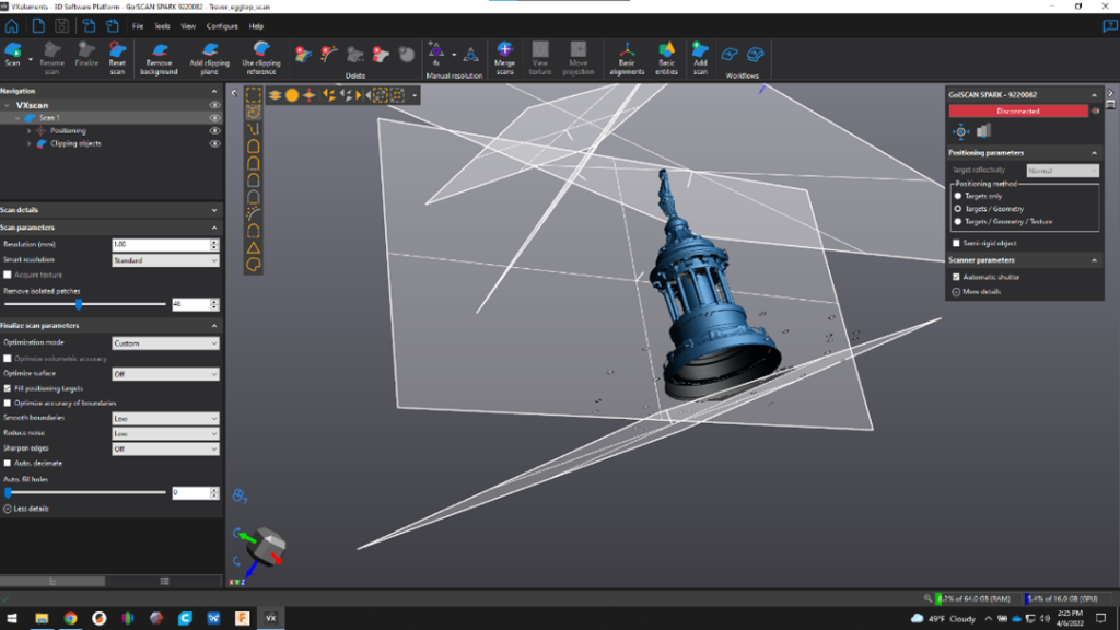
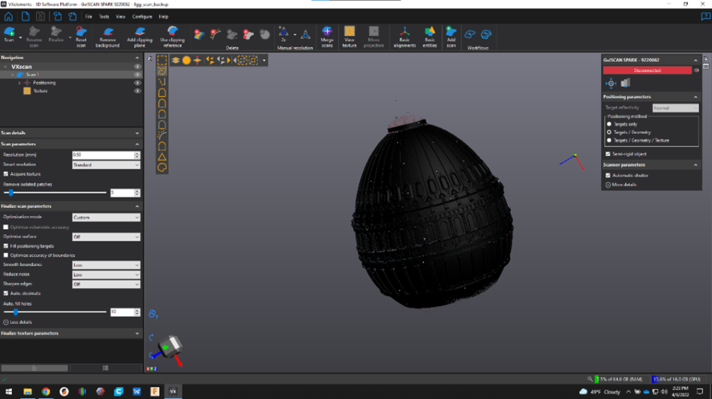
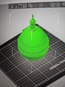
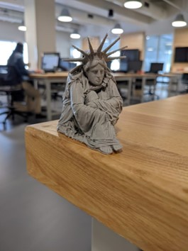
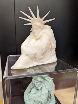
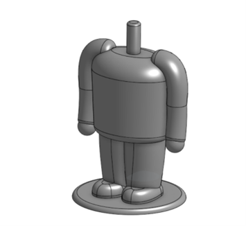
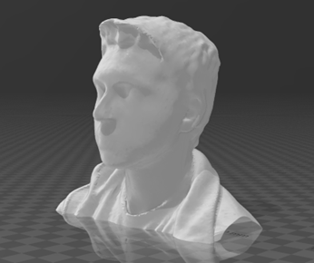
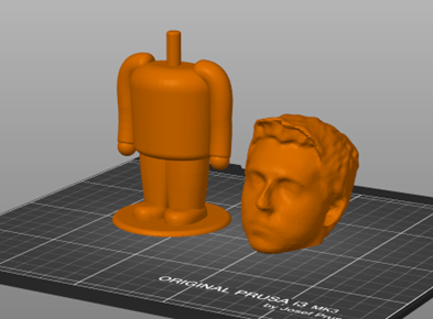
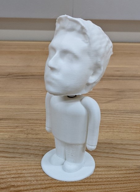
For one of the IDEA Lab events, I decided to make bobble heads of your head for my workshop. I first designed the bobble body using OnShape. This was the body that all attendees were given. To create the head, I first used the Structure Sensor Pro to scan the attendee’s head using the Structure Scanner app on an iPad to create an STL model. I sent the model to my computer and opened the STL file in Microsoft 3D Builder. I edited the model to fit the springs and connect to the body. I used the Prusa MK3S print farm to print the bodies and heads.
Equipment/Software:
- OnShape
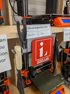
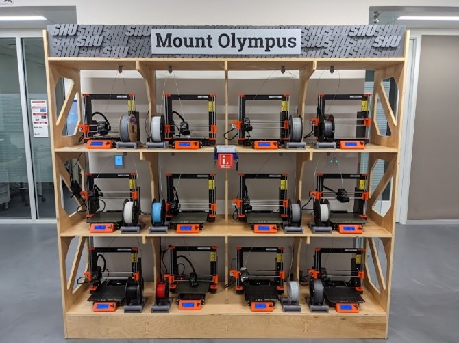
- Prusa MK3S
- Microsoft 3D Builder
- Structure Sensor Pro
- Structure Scanner App
- iPad Pro 10th Generation
- Springs
Step by Step:
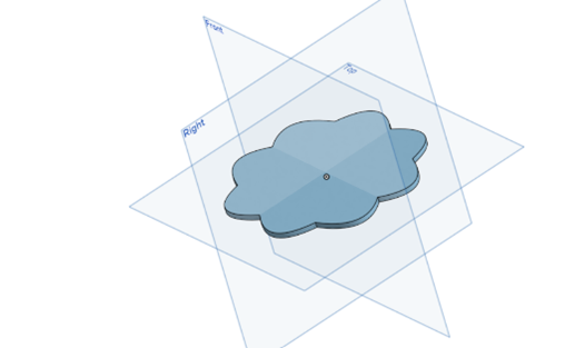
- Designed the body in OnShape
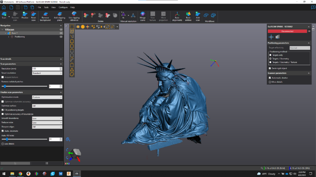
- Create a scanned head using the iPad scanner, and sent to 3D Builder
- Trim the head
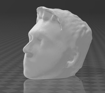
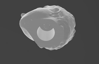
- Import the bobble spring attachment, which is the negative that will be subtracted from the inside of the head
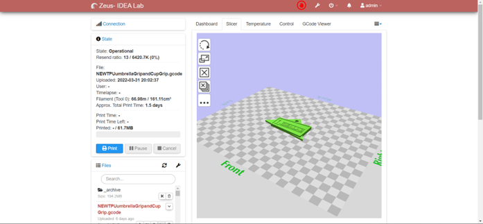
- Export the model and import the body and head into PrusaSlicer
- Assemble the design, cut spring in half and hot glue the head to the spring, and the body to the spring
The challenging part with this project was to find a simple way to add the spoke for the spring to attach to within the head. At first, I tried to subtract a cylinder hole from the head, then add another cylinder for the spring to attach to. The issue with this was that it was difficult to get the spoke and hole to get the correct dimensions each time. I then came up with a solution by creating the negative space of the hole and spoke in CAD, and then subtract the negative from the head. This left the spoke and hole the same for each head.
Through the development of this workshop, I learned a more in-depth usage of CAD programs; problem the creation of more organic models (arms in the body). I also learned more techniques in creating 3D scans of people’s heads and further modifying them to fit our needs.