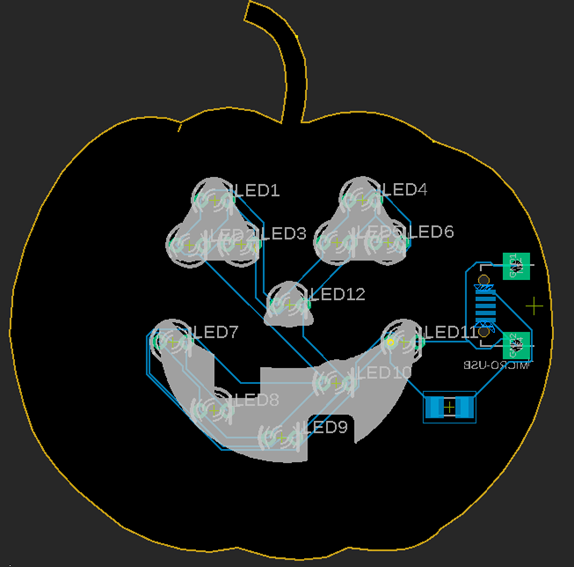
I designed a custom PCB in the shape of a pumpkin for Halloween. It uses LEDs and a micro-USB connector to power it.
Equipment/Software:
- Eagle PCB
- PCBWay
- LEDs
- Resistor
- Micro-USB
- Soldering Iron
- Solder
- Fume extractor
Step by Step:
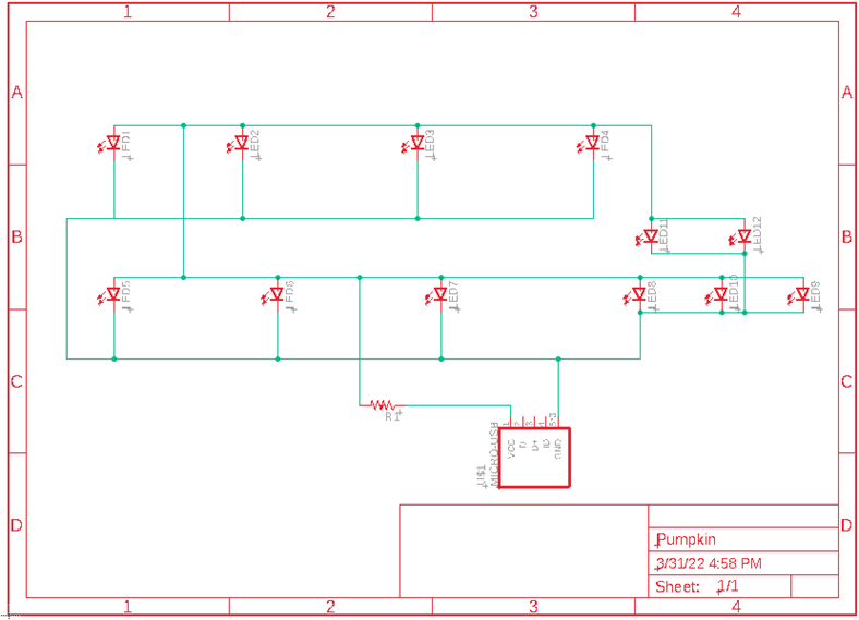
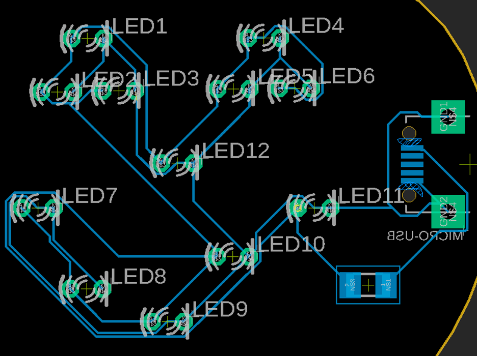
- Designed the PCB in Eagle
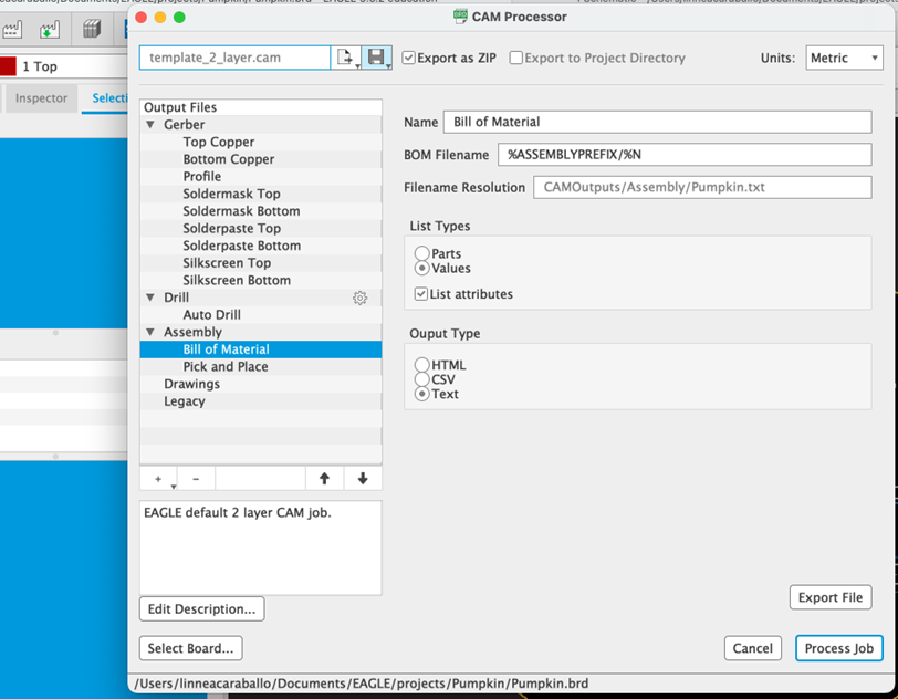
- Go to CAM Processor and export as a zip folder
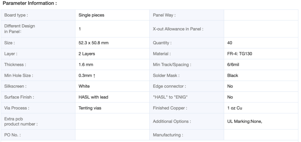
- Go to PCBWay and upload dimensional information and upload zip file
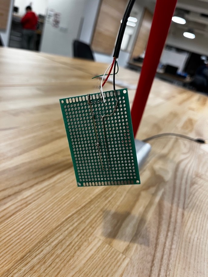
- Pre-solder the USB Micro connectors and resistor to the PCBs using solder paste
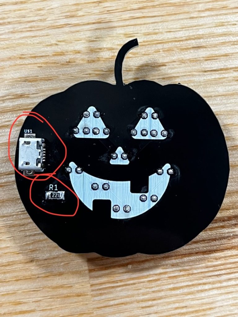
- Be aware of the anode and cathode according to this diagram (flat side is the ground/cathode)
- Test
It was challenging making sure that all the files were correct for manufacturing the PCB. I learned how to make custom shapes for PCBs.