Categories
3d printing CAD - Design machine shop Programming Project

Prusa Print Farm

by Trevor Neal and Bryan Bushey

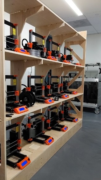
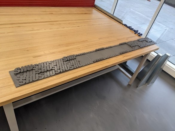
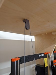
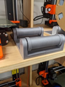
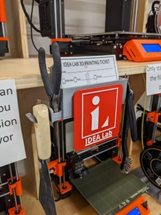
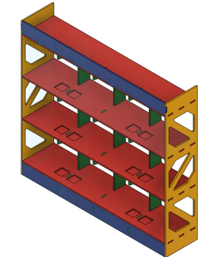
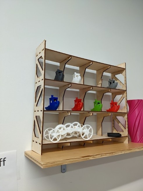
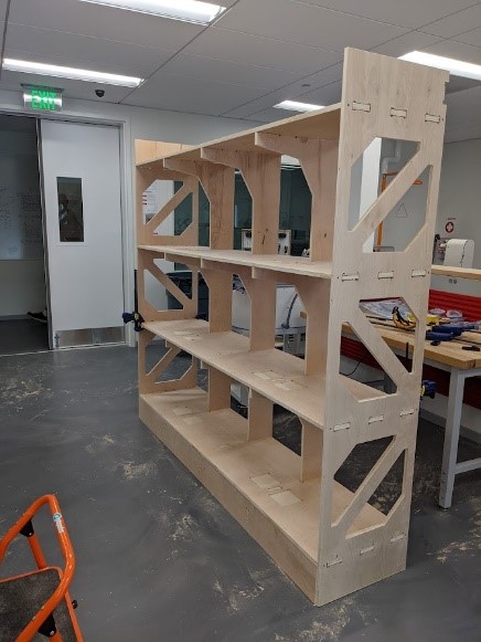
For the arrival of 12 new Prusa MK3S+ 3D printers, we needed to design a system to streamline the 3D printing process for new and returning users. We created a large shelf to store the printers by first using Fusion 360 to implement the design. We then created a scale model to accurately determine measurements. Next, we cut on the lab’s ShopBot CNC machine. Once all the pieces were cut, we assembled the shelf and sanded at 220 grits. Applying a polyurethane finishing after. When the wall was complete, we designed 3D printed filament spool rollers and pulleys to allow easy access for changing the printer’s filament. After, we designed a 3D printed sign to label our print farm, “Mount Olympus”, since we named all 12 of our printers after the 12 Greek Gods.
            Our goal with the usability of the print farm was to create an online website that allows users to select one of the lab’s Prusa 3D printers, upload their model, have it sliced using our custom profile, and automatically start the sliced print. We decided to use OctoPrint. OctoPrint is a fully open-source web server/interface to directly connect to a 3D printer. Originally, OctoPrint was designed to be installed on Raspberry Pi computers, since we had 12 printers, we wanted one system to do everything.

Equipment/Software:

  • Fusion 360
  • OnShape
  • ShopBot
  • Epilog Fusion Pro 48 Inch
  • 3mm Plywood
  • ¾ inch Plywood
  • Linux Docker
  • OctoPrint
  • Overture PLA
  • 22mm Ball Bearings

Step by Step:

  • Designed the shelf in Fusion 360 and exported the file as a DXF
  • Laser cut out a scale model on the Epilog Fusion Pro in wood, using 3mm plywood
  • Cut out the finished design on the ShopBot using ¾ inch plywood
  • Assemble the cut design (nail gun/wood glue/sanding 220 grit)
  • Finished wood with polyurethane
  • Designed spool rollers, pulleys, and wall-sign in CAD
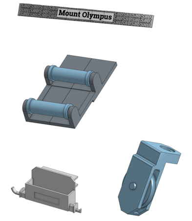
  • 3D printed designs and installed on the shelf
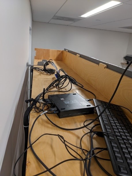
  • Computer formatted to run Linux, with Docker instances installed

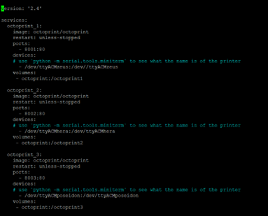
Using a standard desktop computer, we downloaded and installed Debian Linux to run 12 different docker instances of OctoPrint designed specifically to work for docker.

  • Create profiles for OctoPrint on each instance and install the web slicer
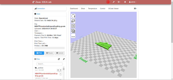
  • Connect printers to their respective instance
  • Create website using HTML, CSS, JavaScript
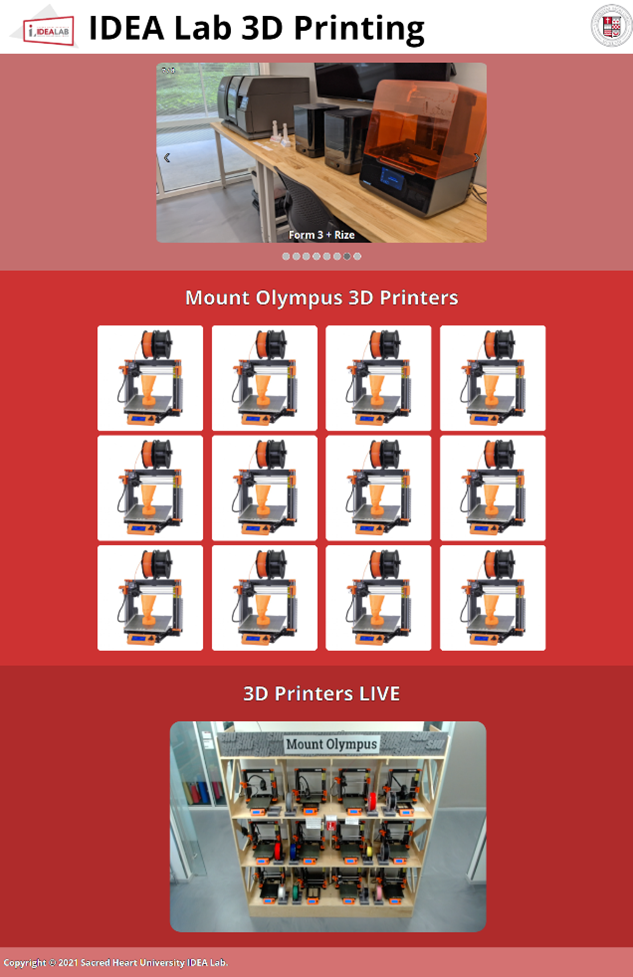
To make using the print farm easier to the end user, we created an HTML page that displayed links to each of the instances as well as a live webcam feed to visually monitor the printers.

  • Webcam installation

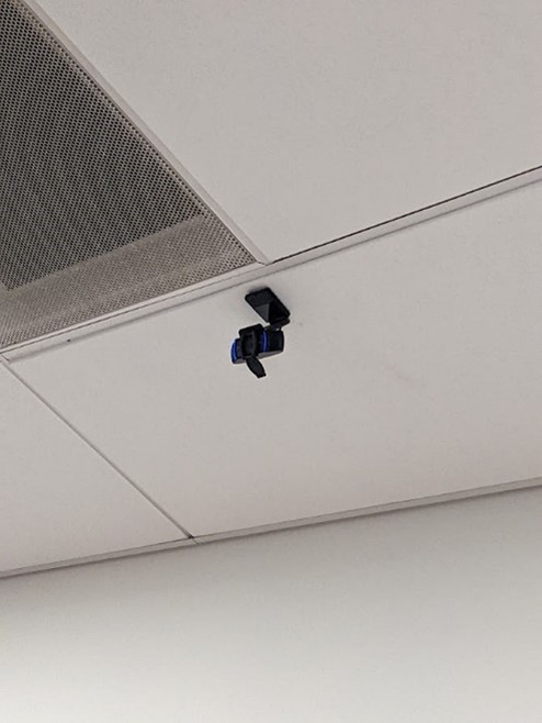
We wanted to also create a live webcam feed to accurately monitor on-going prints. To do so, we connected a webcam to the Linux computer and created a new docker instance for the webcam.
  • Finished

One of the main challenges with this project was to get the computer functional with 12 instances of OctoPrint using Docker. We continued to run into problems on getting the OctoPrint slicer plugin to be functional. We overcame this by researching documentation on the slicer plugin and found the correct install information for Linux. Setting up the webcam had its own issues. When creating the webcam Docker instance, the recommended image file we decided to use did not function correctly, so after trying newer images, one finally produced the results we were looking for.

During this project we learned many new and innovative ways to create a 3D printing farm. For us, we learned a lot about how docker, and its instances work on Linux systems. Creating the website allowed us to learn HTML, CSS, and JavaScript together.

Categories
CAD - Design machine shop Project

Computer Stands

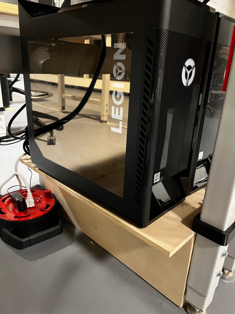
I designed computer stands so that we could keep the two computers in the main space at the Idea Lab between the two desks.

Equipment/Software Used:

  • Plywood
  • Fusion 360

Final

The final design was created in Fusion 360 and used finger joints to join the base and the legs. The space between the legs of the desks were measured and multiple prototypes were used to make sure that the computer holders fit perfectly. There were two drill holes in the top, this allowed us to bolt down the holders. Thus, preventing them from moving. The computers then sit on top of the stand.

Categories
3d printing CAD - Design machine shop Project

Front Desk at the Makerspace

by Bryan Bushey and Trevor Neal

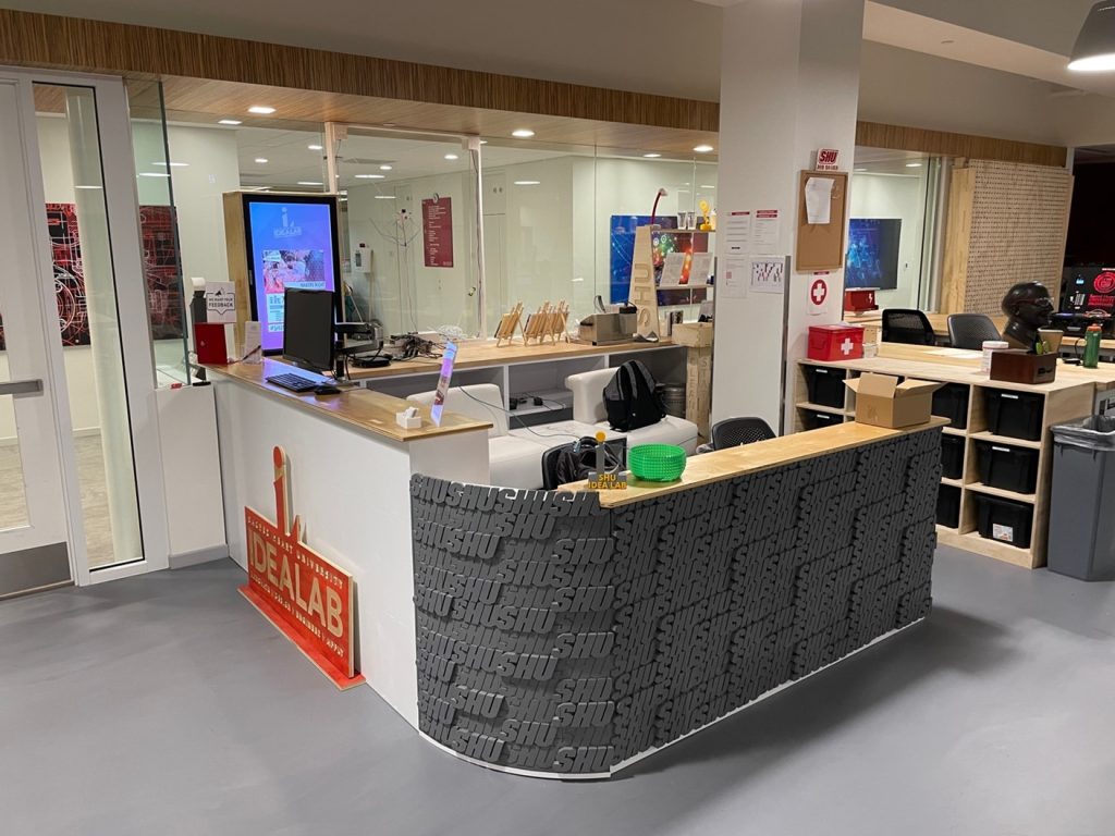
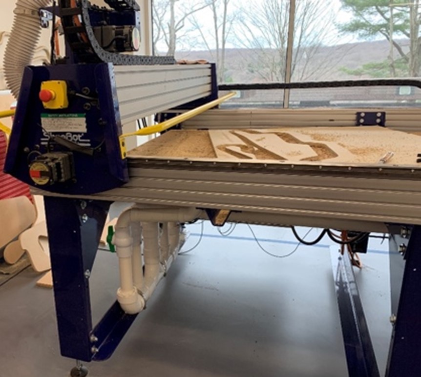
We designed the front desk of the makerspace at Sacred Heart University by using the Fusion 360 CAD software and the CNC Router known as the ShopBot. This wooden desk is used each day by staff as a receptionist desk. The second part of the desk is used for staff storage, and it holds a welcoming monitor for visitors.

Equipment/Software:

  • Autodesk Fusion 360
  • ShopBot
  • Epilog Fusion Pro 48 Inch
  • ¾ inch 4ft x 8ft Plywood
  • 3mm 12in x 24in Plywood

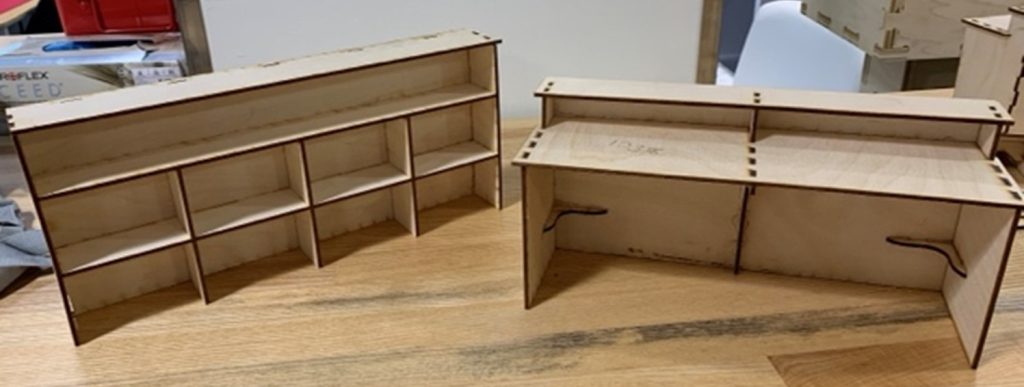
We designed the front desk using Fusion 360 keeping the thickness of the stock and multiple other measurements as ‘parameters,’ allowing us to alter the measurements seamlessly depending on future need-based changes. Some difficulties were that the wood sourcing in the design phase vs the final product. When we initially designed the desk there was supposed to be a sheet of butcher block. After some logistical challenges, we ended up deciding on a single ¾ inch sheet with stain to give it a polished look. The sides were painted white to match the surrounding room.

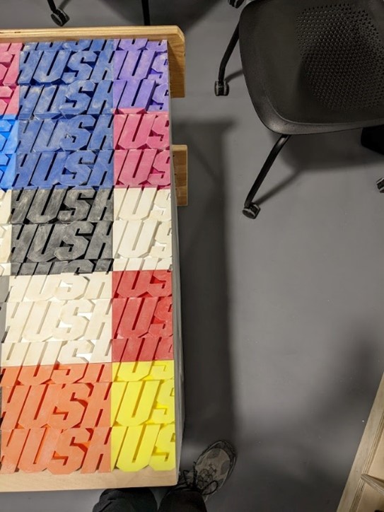
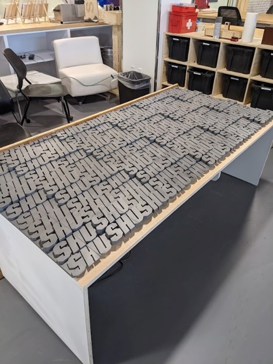
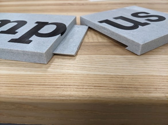
We worked on the 3D printed SHU wall that wraps around the model. To get the ‘SHU’ wall to look flush, we had to sand the entire face and apply multiple coats to get a smooth even finish. We only had a 3D printer bed size of no more than 12 x 12 inches, we had to slice the wall into 50 separate pieces for the flat section alone, and 24 pieces for the curved section.

To ensure the finger joints were appropriately placed, we cut out scale models. By scaling the 3/4in plywood to the 3mm plywood, the models were the exact proportions that the final product would be.

The main challenge was keeping in mind all the add-ons like the monitor and outlets. When designing it is easy to forget about the real-world parts that play into the design after it is built. Also being one of my first major CNC projects with the ShopBot, we did not have much experience with tolerances. By designing the CAD model with an exact thickness of 3/4 of an inch, it was harder to fit the finger joints together as there was zero give between parts. For this project on we used 18mm as the thickness because it allowed for a more forgivable distance that was more realistic.

Categories
CAD - Design machine shop Project

Paper Dispenser

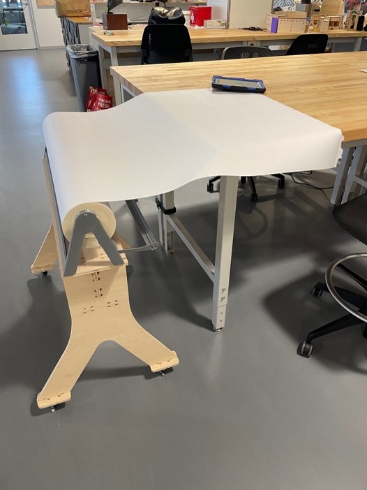
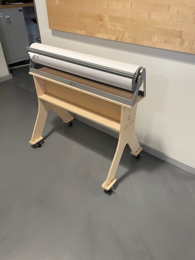
The Design for this vacuum hub came about from my paper roller design. Within the main workshop we often hosted activities that would cover the tables in hard-to-remove products and stains. With this issue, we ordered a large roll of paper to be cut and laid out across the tables to better protect them. But with this large roll, there was no way to properly move it around to cover the tables in an easy fashion. I was tasked with fabricating a mobile holder where I made the following design to be put on casters.

Categories
CAD - Design machine shop Project

Vacuum Gate

by Bryan Bushey and Trevor Neal

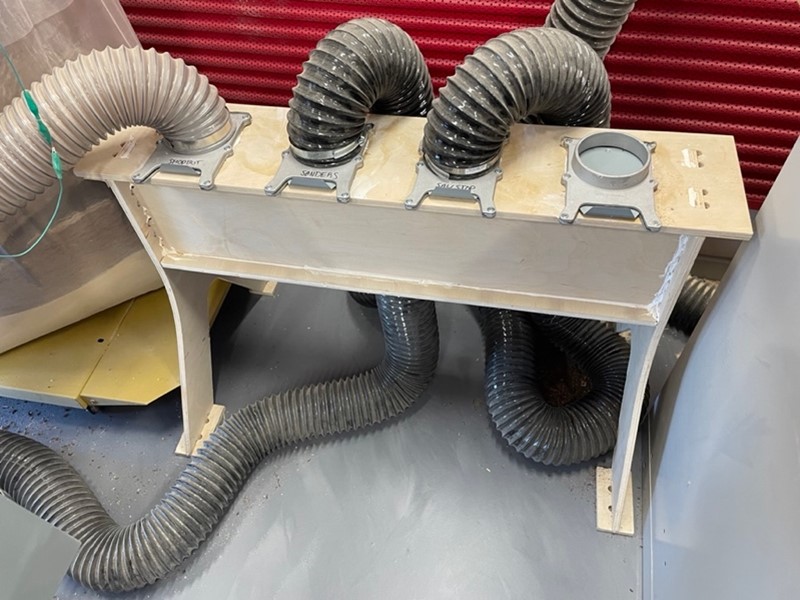
Within the machine shop we have many wood working machines that need vacuuming to keep the air clean and breathable. The vacuum in the shop is a PowerMatic with dual filters and bags. With the loss of suction by hooking up the three other machines to the vacuum created a loss of suction to the ShopBot. This was causing a lack of a safe operation. A challenge with the ShopBot is making sure there is no build-up of sawdust around the drill bit. When there is flammable sawdust near a drill bit, it creates a massive amount of friction that can only lead to one problem. To solve this, I designed and built a four-way switch. The gates on every outlet. This allows me to turn off the vacuum to certain machines and give power to the one in use. The previous method for this was physically removing and replacing the 4-inch pipe.

One issue for designing was keeping an air-tight seal. By using finger joints, this opened holes in the final product for the CNC paths of the production. With the help of Trevor Neal, he created 3D printed plugs to fill the holes along with a silicon caulk gun to fill the seams between planes.

Categories
CAD - Design machine shop Project textiles

Pull Out Drawer

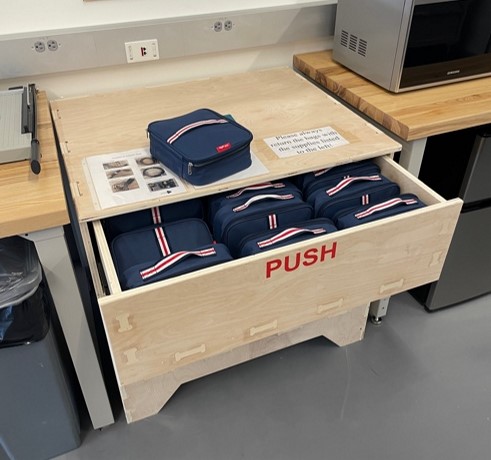
The Engineering department at Sacred Heart University created an electronics kit that included the necessary equipment to conduct their classes. The issue was there was a lack of storage in the space for them. Originally, I was tasked with creating a shelf to store them, but we soon realized that the boxes on the bottom would be too difficult to reach on a regular basis. My team and I settled on a pull-out drawer. I designed a drawer to hold all 16 kits as well as have room below to store two large containers with extra supplies.

After some measurements and evaluations, I was able to drill in place the rails which are rated to handle up to one hundred pounds when fully extended. This was necessary because of the weight of the drawer itself was constructed out of ¾ inch plywood.

My main problem with the drawer was a miscalculation of the placement as the rails have a push-to-open mechanism. When pushed incorrectly the drawer would not open making it difficult to open the drawer. After moving the rails and cutting back some of the panels, I made the drawer flush, thus making it a press to open.

Categories
CAD - Design machine shop Project

Arcade Joystick

by Trevor Neal and Massimo Bacchiocchi

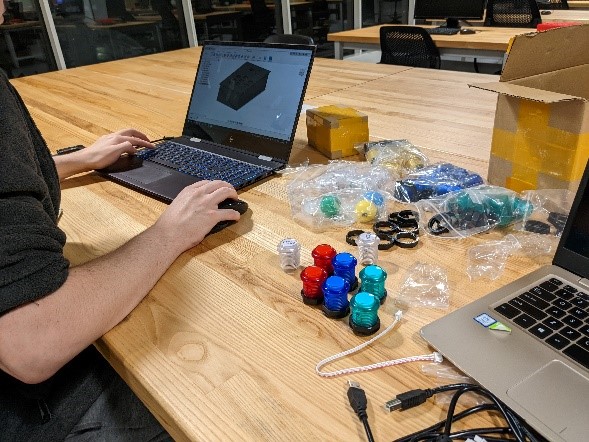
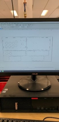
This event lets students build their own arcade joystick controller. It can be used with PC’s, Raspberry Pi’s and other emulators. The case for the arcade stick was designed in Fusion 360. Then, exported as dxf files and combined in CorelDRAW to fit on one 12 x 24 inch sheet of 3mm plywood. The combined file was laser cut on the Epilog Fusion Pro. The PCB, buttons, and joystick are all plug and play with no soldering required making it very easy for students to build. The PCBs are programmed using an emulation software or front end like retropie or libretro. They should be able to be remapped in games such as street fighter V on PC.

Equipment/Software:

  • Fusion 360
  • CorelDRAW
  • 3mm Plywood
  • EG starts Arcade Joystick lever
  • EG starts Light up Arcade buttons
  • EG starts Arcade stick PCB
  • M3 Screws
  • M3 nuts
  • M4 Screws
  • M4 Nuts
  • Epilog Fusion Pro Laser Cutter

Step by Step:

  • Designed the container in Fusion 360
  • Exported the file as a DXF
  • Laser cut out all the pieces on the Epilog Fusion Pro
  • Test fit the pieces
  • Screw in all the buttons and stick to the top case
  • Install the front two buttons
  • Screw the PCB board into the bottom of the container
  • Assemble the sides, plug in all the wires into the PCB, the buttons, and stick
  • Fully assemble the joystick controller

During the creation of the container housing the joystick, one of the challenges we overcame was determining how to best fit the button layout on the top face of the controller. We looked to the internet to see official designs of actual full-sized arcade cabinets and based our layout on theirs.  

Through this project we learned a lot about designing laser-cuttable containers in Fusion 360. I learned how to break down the full container model into different components making up each face. They could then be laser cut and slotted-in together.

Categories
3d printing CAD - Design Electronics - Arduino machine shop Project

Custom LED Lamps

by Bryan Bushey, Linnea Caraballo, and Trevor Neal

We designed custom LED lamps using LEDs and protoboards.

Equipment/Software:

  • 3D Printer
  • Wood
  • Soldering Stations
  • LEDs
  • USB Cable
  • Spray Paint

Electronics

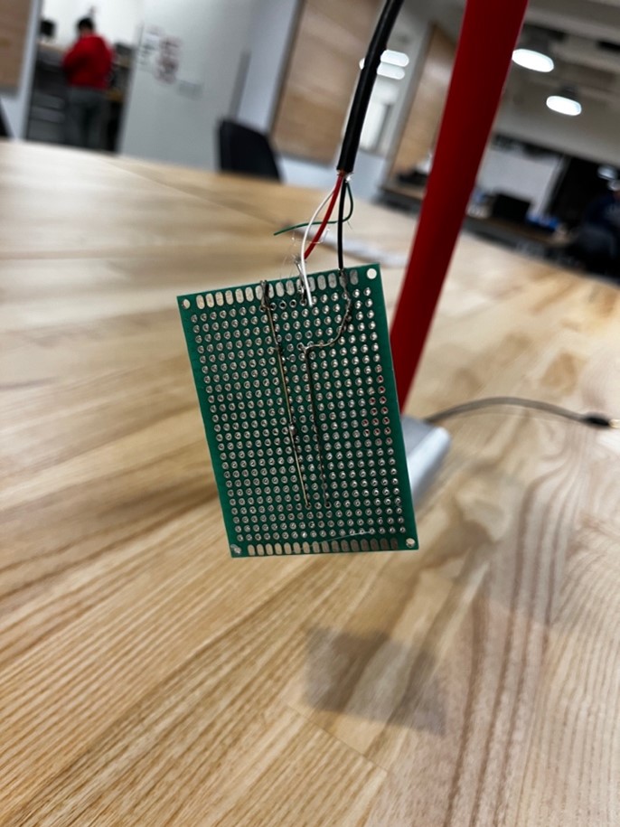
We soldered 3 LEDs in parallel using a protoboard. We then took a micro-USB cable and cut off the USB end and stripped the wires so that it exposed the power and ground cables. We then soldered these to the LEDs so that they could be powered.

Final

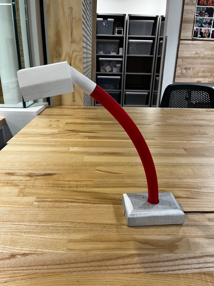
The final design for the LED lamp was using a 3D printed lamp shade, a wooden base, and reusing hula-hoop parts to make the arm of the lamp. We then spray painted the base and hula-hoop part.

            This was one of the first electronic projects and workshops done, so it was a good way to get the hang of running workshops. It was also one of the first collaborative projects between multiple staff members and it allowed us to reuse parts that we no longer needed without having to throw them out.