Categories
CAD - Design Project textiles

Fashion Class

Sacred Hearts Fashion Innovation 299 course for the first half of the semester teaches innovation in the business world. For the second half of the semester, I took over teaching the class by training them in multiple badges including 3D printing, sublimation printing, and vinyl cutting. Before the class started at the makerspace, I took the assignments and projects they had to do in the makerspace, created a lesson plan, and created PowerPoints to open the different badge trainings. The lesson plan gives them time to get their badges as well as use the machines frequently, as well as make sure there is time allotted for their final project. Teaching the class involved multiple presentations to the class as well as teaching material and one on one work with students and groups to refine their work. Once they started working on the final, I was there as an aid to bounce ideas off and help make their dreams a reality with the use of the lab equipment.

LESSON PLAN OVERVIEW

  • 10/8 – Makerspace Tour and Overview of Technologies
    • PowerPoint about what the makerspace is
    • Tour with manager
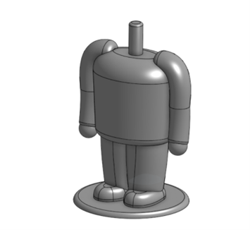
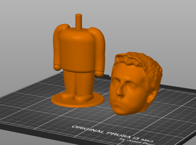
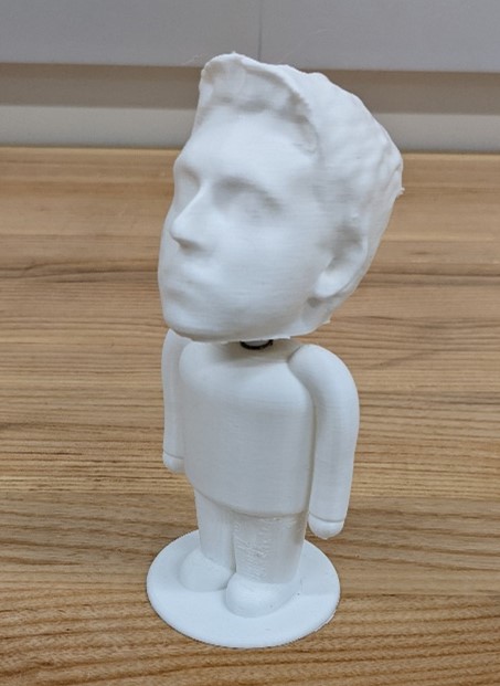
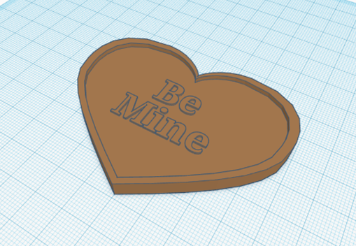
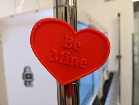
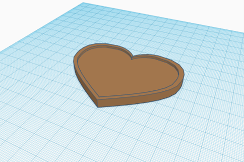
  • 10/15 – 3D Printing Exercise: Part 1
    • Individual Project
      • Find a small print on Thingiverse
      • Slice it
      • Can be anything
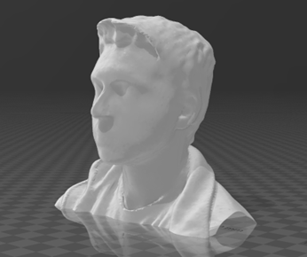
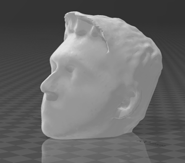
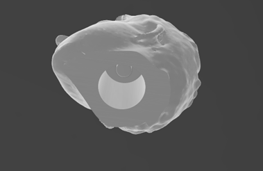
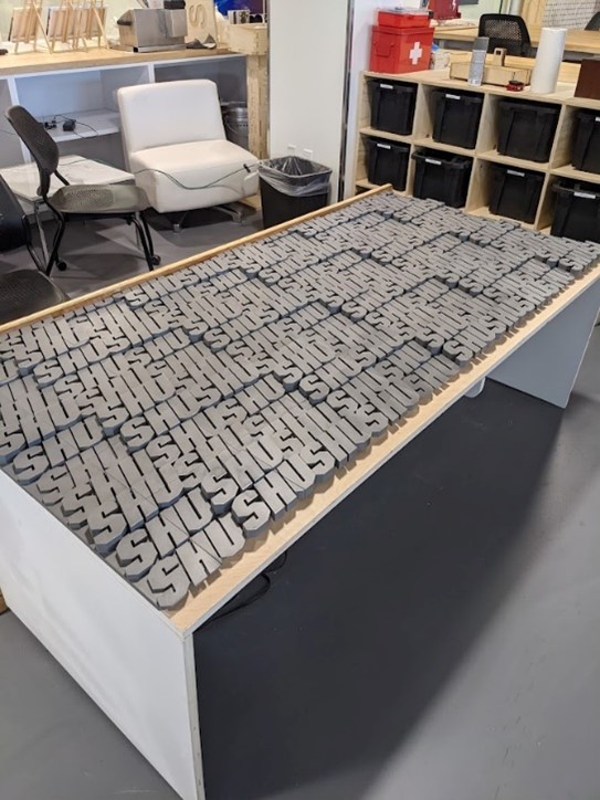
  • 10/22 – 3D Printing Exercise: Part 2
    • Group Project
      • Theme “mask up”
      • Ideation session alone on what they want to make
      • Sessions includes:
        • Post it notes/word cloud
        • Reflect on the notes
        • Develop a sketch that represents your thoughts on the theme
      • Connect with your group and share your ideation process and designs
      • Center on one idea and create a proposal
      • Present the team proposal to manager/myself/class
      • Work with Cedric and makerspace team to design and execute your idea
  • 10/29 – Sublimation Printing
    • Introduction to sublimation printing via my PowerPoint
    • Teach them how to use Sawgrass to create
    • Ideation on the golden circle
    • Create a sketch, then recreate it in Sawgrass
    • Print out the design on the Sawgrass printer
    • Use the heat press to transfer the design
  • 11/5 – Vinyl Cutter
    • 10min – Dr. Dave presentation on vinyl cutting in fashion
    • How to use CorelDRAW all together
    • Badge training for the vinyl cutter by groups
    • Create and transfer your design in the makerspace
  • 11/12 – Final Project Phase 1 and 2
    • Ideation with group
    • Value Proposition and BMC sketching
  • 11/19 – Final Project Phase 3
    • Present your ideas to the class and get feedback
    • Continue to use makerspace tech for projects
  • 12/3 – Final Makerspace Day
    • Last day to work on project

Categories
3d printing CAD - Design Project

Bobble Heads

For one of the IDEA Lab events, I decided to make bobble heads of your head for my workshop. I first designed the bobble body using OnShape. This was the body that all attendees were given. To create the head, I first used the Structure Sensor Pro to scan the attendee’s head using the Structure Scanner app on an iPad to create an STL model. I sent the model to my computer and opened the STL file in Microsoft 3D Builder. I edited the model to fit the springs and connect to the body. I used the Prusa MK3S print farm to print the bodies and heads.

Equipment/Software:

  • OnShape
  • Prusa MK3S
  • Microsoft 3D Builder
  • Structure Sensor Pro
  • Structure Scanner App
  • iPad Pro 10th Generation
  • Springs

Step by Step:

  • Designed the body in OnShape
  • Create a scanned head using the iPad scanner, and sent to 3D Builder
  • Trim the head
  • Import the bobble spring attachment, which is the negative that will be subtracted from the inside of the head
  • Export the model and import the body and head into PrusaSlicer
  • Assemble the design, cut spring in half and hot glue the head to the spring, and the body to the spring

The challenging part with this project was to find a simple way to add the spoke for the spring to attach to within the head. At first, I tried to subtract a cylinder hole from the head, then add another cylinder for the spring to attach to. The issue with this was that it was difficult to get the spoke and hole to get the correct dimensions each time. I then came up with a solution by creating the negative space of the hole and spoke in CAD, and then subtract the negative from the head. This left the spoke and hole the same for each head.

Through the development of this workshop, I learned a more in-depth usage of CAD programs; problem the creation of more organic models (arms in the body). I also learned more techniques in creating 3D scans of people’s heads and further modifying them to fit our needs.

Categories
3d printing CAD - Design machine shop Programming Project

Prusa Print Farm

by Trevor Neal and Bryan Bushey

For the arrival of 12 new Prusa MK3S+ 3D printers, we needed to design a system to streamline the 3D printing process for new and returning users. We created a large shelf to store the printers by first using Fusion 360 to implement the design. We then created a scale model to accurately determine measurements. Next, we cut on the lab’s ShopBot CNC machine. Once all the pieces were cut, we assembled the shelf and sanded at 220 grits. Applying a polyurethane finishing after. When the wall was complete, we designed 3D printed filament spool rollers and pulleys to allow easy access for changing the printer’s filament. After, we designed a 3D printed sign to label our print farm, “Mount Olympus”, since we named all 12 of our printers after the 12 Greek Gods.
            Our goal with the usability of the print farm was to create an online website that allows users to select one of the lab’s Prusa 3D printers, upload their model, have it sliced using our custom profile, and automatically start the sliced print. We decided to use OctoPrint. OctoPrint is a fully open-source web server/interface to directly connect to a 3D printer. Originally, OctoPrint was designed to be installed on Raspberry Pi computers, since we had 12 printers, we wanted one system to do everything.

Equipment/Software:

  • Fusion 360
  • OnShape
  • ShopBot
  • Epilog Fusion Pro 48 Inch
  • 3mm Plywood
  • ¾ inch Plywood
  • Linux Docker
  • OctoPrint
  • Overture PLA
  • 22mm Ball Bearings

Step by Step:

  • Designed the shelf in Fusion 360 and exported the file as a DXF
  • Laser cut out a scale model on the Epilog Fusion Pro in wood, using 3mm plywood
  • Cut out the finished design on the ShopBot using ¾ inch plywood
  • Assemble the cut design (nail gun/wood glue/sanding 220 grit)
  • Finished wood with polyurethane
  • Designed spool rollers, pulleys, and wall-sign in CAD
  • 3D printed designs and installed on the shelf
  • Computer formatted to run Linux, with Docker instances installed

Using a standard desktop computer, we downloaded and installed Debian Linux to run 12 different docker instances of OctoPrint designed specifically to work for docker.

  • Create profiles for OctoPrint on each instance and install the web slicer
  • Connect printers to their respective instance
  • Create website using HTML, CSS, JavaScript

To make using the print farm easier to the end user, we created an HTML page that displayed links to each of the instances as well as a live webcam feed to visually monitor the printers.

  • Webcam installation

We wanted to also create a live webcam feed to accurately monitor on-going prints. To do so, we connected a webcam to the Linux computer and created a new docker instance for the webcam.

  • Finished

One of the main challenges with this project was to get the computer functional with 12 instances of OctoPrint using Docker. We continued to run into problems on getting the OctoPrint slicer plugin to be functional. We overcame this by researching documentation on the slicer plugin and found the correct install information for Linux. Setting up the webcam had its own issues. When creating the webcam Docker instance, the recommended image file we decided to use did not function correctly, so after trying newer images, one finally produced the results we were looking for.

During this project we learned many new and innovative ways to create a 3D printing farm. For us, we learned a lot about how docker, and its instances work on Linux systems. Creating the website allowed us to learn HTML, CSS, and JavaScript together.

Categories
CAD - Design Electronics - Arduino Project

PCB Pumpkin

I designed a custom PCB in the shape of a pumpkin for Halloween. It uses LEDs and a micro-USB connector to power it.

Equipment/Software:

  • Eagle PCB
  • PCBWay
  • LEDs
  • Resistor
  • Micro-USB
  • Soldering Iron
  • Solder
  • Fume extractor

Step by Step:

  • Designed the PCB in Eagle
  • Go to CAM Processor and export as a zip folder
  • Go to PCBWay and upload dimensional information and upload zip file
  • Pre-solder the USB Micro connectors and resistor to the PCBs using solder paste
  • Be aware of the anode and cathode according to this diagram (flat side is the ground/cathode)
  • Test

It was challenging making sure that all the files were correct for manufacturing the PCB. I learned how to make custom shapes for PCBs.

Categories
CAD - Design machine shop Project

Computer Stands

I designed computer stands so that we could keep the two computers in the main space at the Idea Lab between the two desks.

Equipment/Software Used:

  • Plywood
  • Fusion 360

Final

The final design was created in Fusion 360 and used finger joints to join the base and the legs. The space between the legs of the desks were measured and multiple prototypes were used to make sure that the computer holders fit perfectly. There were two drill holes in the top, this allowed us to bolt down the holders. Thus, preventing them from moving. The computers then sit on top of the stand.

Categories
3d printing CAD - Design Project textiles

Pi Holder

I designed a custom Raspberry Pi Zero holder for the desks.

Equipment/Software:

  • 3D Printer
  • Raspberry Pi Zeros
  • Ribbon cables/connectors
  • Fusion 360
  • Power cables

Prototype

I was not sure how to execute what I wanted to accomplish with the Raspberry Pi holders. At first, I wanted to attach the holders to the front of the desk legs in the middle so that they were out of the way but still accessible. However, after we 3D printed them, we could not figure out a good way to create brackets to secure them to the desk legs. We also realized that this was impractical, especially if we wanted to use the GPIO pins in the future. This Pi holder design would also make it so that the table couldn’t be moved around since they would bind two tables together meaning that a new Pi holder would need to be designed if the desks were ever separated. This led to us deciding to make Pi holders that will individually sit on top of the desk, yet still look coherent when next to each other in the current setup.

Final

The final design allowed for us to put the Raspberry Pi holders at the corner of a desk with the Raspberry Pi Zero snuggly fitting in and having enough space for the ribbon connectors and power cables. This makes the Pi holders able to hold the Pi’s and the accessories needed to utilize them to their full potential. These Pi holders needed to work effectively, but also be appealing to the eye which inspired the design of the lid. To design the lid, I started by creating a SVG file of triangular patterns then importing that into the Fusion using the extrude tool to create the different depths.

Another thing that I added to the final design was vinyl labels to access the SSH and VNC. To do this, we had to set up two port forwards per Pi allowing for anyone to connect to the Pi’s if they are on Sacred Heat Wi-Fi. This will allow for users to be able to see the full desktop and GUI of the Raspberry Pi with VNC or to just use the command line using SSH. It also allows for all GPIO pins to be accessed and usable with a breadboard making it easy to attach sensors, so the Raspberry Pi’s are fully functional.

Categories
3d printing CAD - Design machine shop Project

Front Desk at the Makerspace

by Bryan Bushey and Trevor Neal

We designed the front desk of the makerspace at Sacred Heart University by using the Fusion 360 CAD software and the CNC Router known as the ShopBot. This wooden desk is used each day by staff as a receptionist desk. The second part of the desk is used for staff storage, and it holds a welcoming monitor for visitors.

Equipment/Software:

  • Autodesk Fusion 360
  • ShopBot
  • Epilog Fusion Pro 48 Inch
  • ¾ inch 4ft x 8ft Plywood
  • 3mm 12in x 24in Plywood

We designed the front desk using Fusion 360 keeping the thickness of the stock and multiple other measurements as ‘parameters,’ allowing us to alter the measurements seamlessly depending on future need-based changes. Some difficulties were that the wood sourcing in the design phase vs the final product. When we initially designed the desk there was supposed to be a sheet of butcher block. After some logistical challenges, we ended up deciding on a single ¾ inch sheet with stain to give it a polished look. The sides were painted white to match the surrounding room.

We worked on the 3D printed SHU wall that wraps around the model. To get the ‘SHU’ wall to look flush, we had to sand the entire face and apply multiple coats to get a smooth even finish. We only had a 3D printer bed size of no more than 12 x 12 inches, we had to slice the wall into 50 separate pieces for the flat section alone, and 24 pieces for the curved section.

To ensure the finger joints were appropriately placed, we cut out scale models. By scaling the 3/4in plywood to the 3mm plywood, the models were the exact proportions that the final product would be.

The main challenge was keeping in mind all the add-ons like the monitor and outlets. When designing it is easy to forget about the real-world parts that play into the design after it is built. Also being one of my first major CNC projects with the ShopBot, we did not have much experience with tolerances. By designing the CAD model with an exact thickness of 3/4 of an inch, it was harder to fit the finger joints together as there was zero give between parts. For this project on we used 18mm as the thickness because it allowed for a more forgivable distance that was more realistic.

Categories
3d printing CAD - Design Project

3D Printed Heart Magnets

For a Valentine’s Day event at the Idea Lab, I created a workshop that let users add their own custom text to a heart shaped magnet using Tinkercad. The Heart Magnets were designed with a 10.2mm x 2.6mm hole in the back to fit in the magnet. The hole was made slightly larger than the magnet so it would friction fit, but the magnets were very strong, so I had to add super glue. This was so the magnets would stay in the heart. This event also teaches the basics of Tinkercad and 3d modeling. This is done by them manipulating the size and shape of 3D models as well as combine objects and export them as STL files.

Equipment/Software:

  • Tinkercad
  • Prusa MK3S+ 3D printers
  • Overture PLA
  • 10mm Magnets
  • Super Glue

Step by Step:

  • Designed the Hearts in Tinkercad
  • Exported the file as STL
  • Created examples of the magnets with generic text to show people during the event what they should expect
  • Made a version of the Heart Magnets without any text so people would be able to add their own during the event

As this project was my first time creating a 3D model from scratch, it was challenging to enhance the shapes of the heart, thus making it more complex. The heart shape I ended up making had a raised border and was large enough to fit at least two lines of text. It was also challenging to teach all the students how to use Tinkercad, make sure their text was a proper size, connected to the 3D model and 3D printable.

It was interesting to do something like this instead of getting a 3D model from Thingiverse and printing it. This has helped my 3D design skill and knowledge. This event also required me teach students how to use Tinkercad. I have had experience teaching students how to use all the different types of equipment here at the Idea Lab because of my job as an Educator, however, this was my first time teaching 40 students how to 3D model.

Categories
CAD - Design machine shop Project

Paper Dispenser

The Design for this vacuum hub came about from my paper roller design. Within the main workshop we often hosted activities that would cover the tables in hard-to-remove products and stains. With this issue, we ordered a large roll of paper to be cut and laid out across the tables to better protect them. But with this large roll, there was no way to properly move it around to cover the tables in an easy fashion. I was tasked with fabricating a mobile holder where I made the following design to be put on casters.

Categories
CAD - Design machine shop Project

Vacuum Gate

by Bryan Bushey and Trevor Neal

Within the machine shop we have many wood working machines that need vacuuming to keep the air clean and breathable. The vacuum in the shop is a PowerMatic with dual filters and bags. With the loss of suction by hooking up the three other machines to the vacuum created a loss of suction to the ShopBot. This was causing a lack of a safe operation. A challenge with the ShopBot is making sure there is no build-up of sawdust around the drill bit. When there is flammable sawdust near a drill bit, it creates a massive amount of friction that can only lead to one problem. To solve this, I designed and built a four-way switch. The gates on every outlet. This allows me to turn off the vacuum to certain machines and give power to the one in use. The previous method for this was physically removing and replacing the 4-inch pipe.

One issue for designing was keeping an air-tight seal. By using finger joints, this opened holes in the final product for the CNC paths of the production. With the help of Trevor Neal, he created 3D printed plugs to fill the holes along with a silicon caulk gun to fill the seams between planes.